
· By Sajeevan (Saj) Veeriah
Engineering case study · 3 min read
Building a ROS 2 navigation stack I could investigate
How I organised sensing, estimation, planning and control for a differential-drive rover, and what simulation could establish.
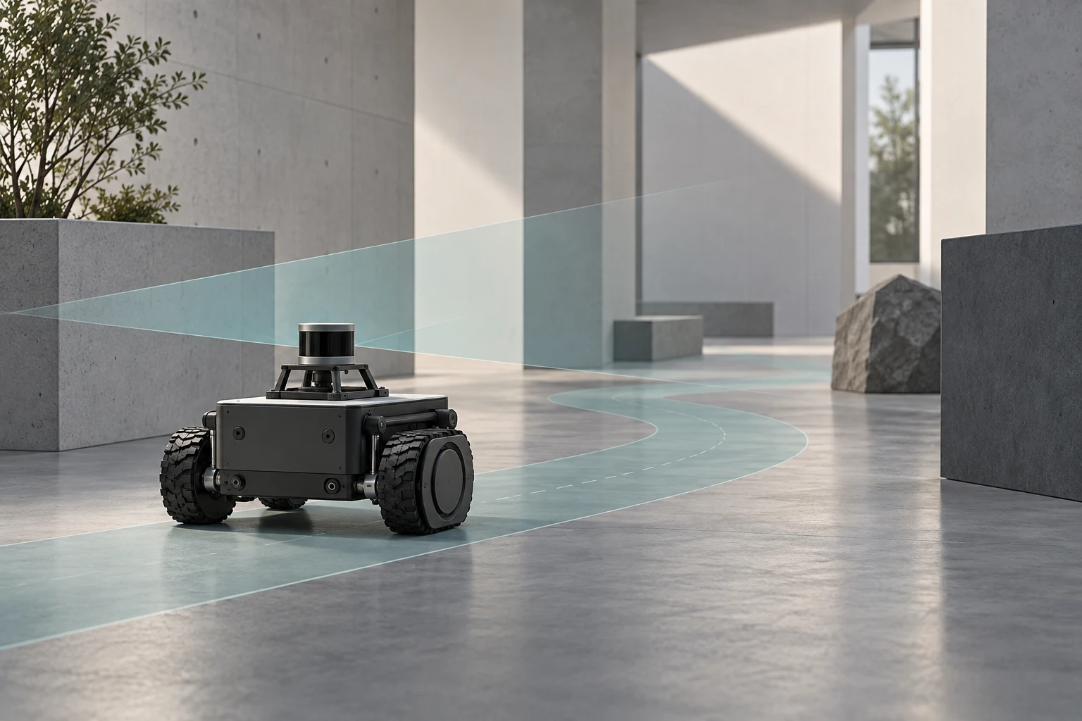
A robot reaching a goal is only part of the engineering problem. I also need to understand how it estimated its position, why it chose a path and what happened when that path became difficult to follow.
For this project, I built a differential-drive platform and integrated a modular navigation stack using ROS 2 Humble, Nav2, LiDAR SLAM, IMU sensing and EKF state estimation. Gazebo Fortress and RViz gave me a repeatable environment for checking the interactions between those parts. The validation described here is simulation-based.
The engineering question
My practical question was how to make localisation, planning and motion control work together while keeping faults traceable to a particular layer. A navigation failure can begin well before the controller: an inconsistent transform or pose estimate can make a reasonable planner appear unreliable.
I treated the system as a sequence of interfaces. Each stage needed an output that the next stage could use and that I could inspect independently.
Sources: [1]
Separating the navigation layers
I kept perception, estimation, planning and control in modular ROS 2 nodes. That separation let me tune one part and inspect its effect across the rest of the stack.
| Layer | Role in this project |
|---|---|
| Sensing and mapping | LiDAR supports SLAM; the IMU contributes motion information. |
| State estimation | EKF fusion provides the pose used downstream, with transforms inspected in RViz. |
| Planning | Nav2 uses the map, fused pose and costmaps to produce a navigable path. |
| Control and recovery | Motion control follows the path; recovery behaviour handles navigation interruptions. |
What I checked
I used Gazebo Fortress regression runs and RViz inspection to examine maps, transforms, fused pose, planned paths and recovery behaviour. Planning, costmap settings and controller gains could be revisited without changing every part of the system at once.
The useful result was an integrated navigation workflow whose intermediate behaviour could be inspected. I am not presenting a numerical localisation benchmark, a measured success rate or a comparison against another navigation system here; this public case study does not include the underlying run dataset needed for those claims.
Sources: [1]
What the simulation leaves open
Simulation supported integration and repeatable investigation. It does not establish performance on an unseen physical floor, under wheel slip or with the timing and sensing imperfections of a deployed robot.
A useful next experiment would hold the route and obstacle arrangement constant, repeat trials across controlled perturbations and record goal completion, path length, localisation behaviour and recovery events. I would compare those runs before claiming a particular design change improved reliability. This is a proposed extension, not a reported experiment.
What I would carry into research
This project made the interfaces between subsystems the centre of my debugging process. For future robotics work, I want an experimental question, observable intermediate states and a clear boundary between what a simulation demonstrates and what still requires a physical trial.
Sources and further reading
First-person engineering case study based on my project record. This is not a peer-reviewed paper or a claim of a novel navigation algorithm. Published 18 September 2026; this is the article date, not the project start date.