
· By Sajeevan (Saj) Veeriah
Robotics / mechatronics / design study · 12 min read
Designing a waterless solar-panel cleaning robot
CAD, traction and energy calculations, conservative coverage planning and an experimental roadmap for a modular dry-cleaning crawler.
A solar-panel cleaner must remove contamination while protecting the surface that produces the energy. Adding a brush to a mobile platform leaves most of that problem unresolved: contact force, embedded grit, wheel slip, edge detection and power-loss retention all interact.
My new design explores a waterless crawler with replaceable track pods, a 420 mm roller and separate docking and loading modules. The goal is a system that can adapt within a qualified installation class. It cannot responsibly mean driving onto any unfamiliar panel and learning its safety limits by trial and error.
This is a development design study. The package contains FreeCAD and STEP models, first-pass calculations, an interface schematic, a tested host-side supervisor and an offline rectangular coverage planner. It does not contain a production-ready robot, a completed electrical safety circuit or evidence of physical cleaning performance.
1. Frame the research question around useful cleaning
My research question is how a lightweight dry-cleaning platform could remove loose contamination while maintaining traction, staying within a known surface and limiting contact damage. Cleaning effectiveness, coverage and surface preservation must be measured separately.
A useful hypothesis would be that a specified roller material and normal force can remove a defined soil load without exceeding a pre-agreed optical or surface-damage limit. A second hypothesis concerns repeatable motion under that same contamination. Neither has been experimentally established for this design.
This changes component selection. More brush force may improve removal while reducing track loading and increasing drag. A wider head may improve nominal area rate while worsening access near frames. A heavier battery may extend energy capacity while increasing glass and mounting loads. These are coupled decisions, not independent catalogue choices.
2. What the CAD actually defines
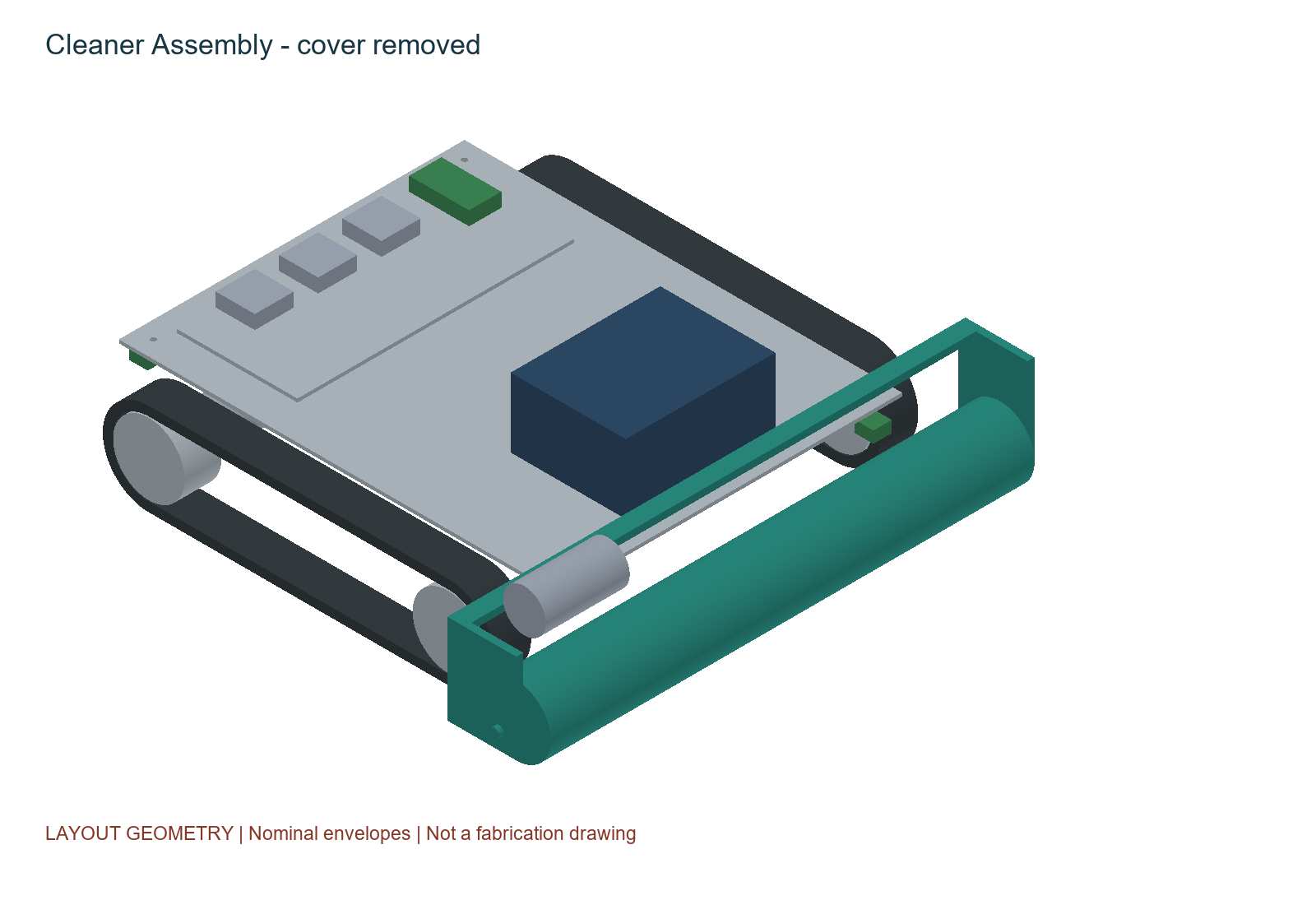
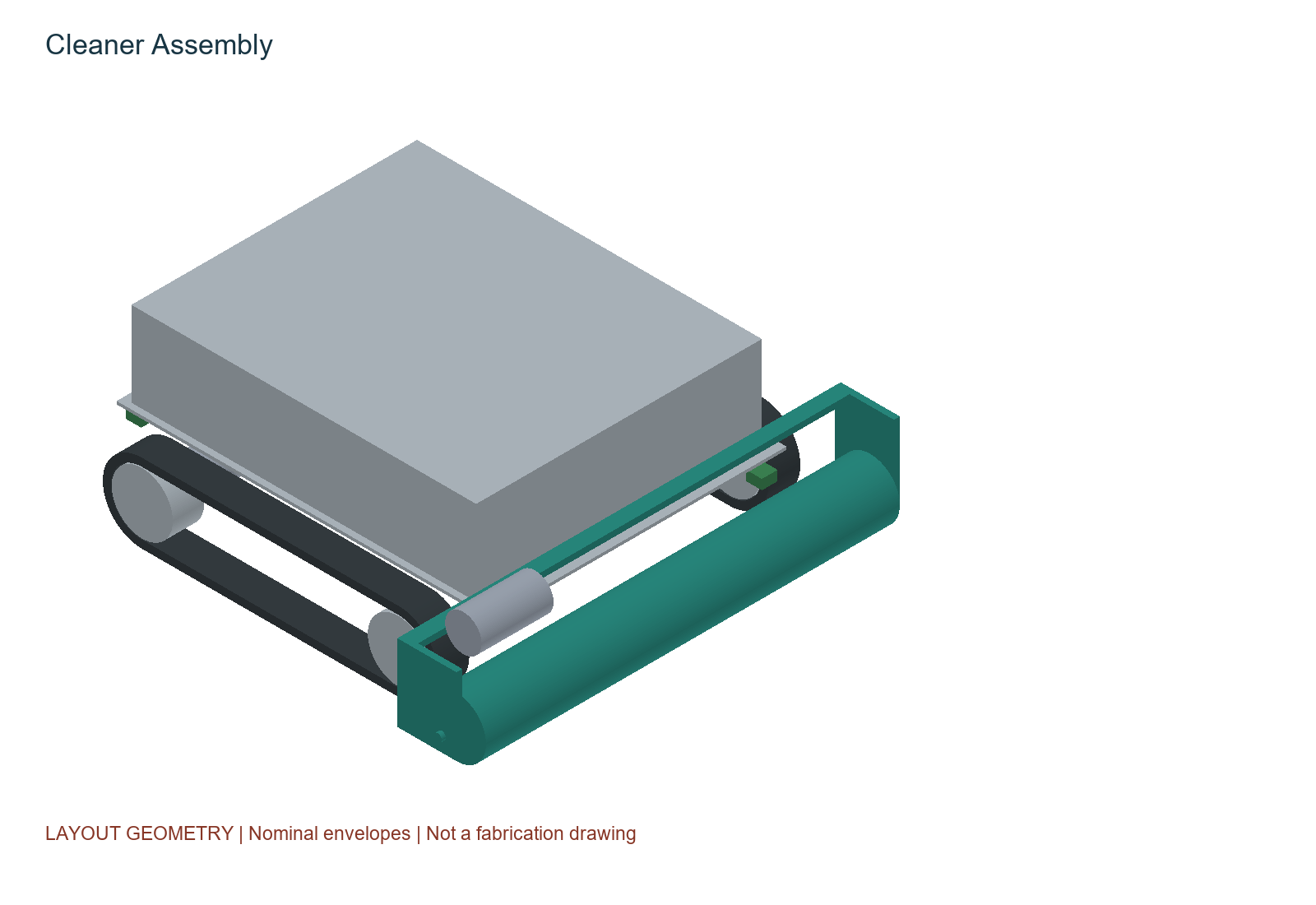
The cleaner model contains 27 named solids within a recorded 438 × 458 × 171 mm bounding box. A 380 × 300 × 3 mm chassis plate carries the battery and electronics allocations, with separate side track pods and the front cleaning roller. The cover is a nominal 3 mm shell.
The geometric model communicates arrangement, access and modularity. Bearings, tensioners, shaft retention, fasteners, transmission details, a compliant brush lift, cable routing, sealing and thermal paths still need detailed design. The four nominal chassis mounting holes do not make the assembly build-ready.
A valid solid and a matching STEP volume establish geometry consistency. They do not prove that a selected battery fits, the chassis will remain sufficiently stiff, or the contact system will avoid damaging a module. The source receipt records successful native/STEP reopening; this publication does not claim a new FreeCAD structural analysis.
3. Start with force balance, then challenge the assumptions
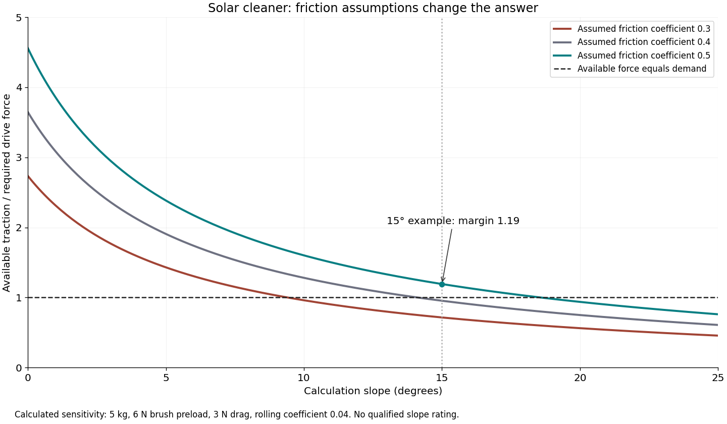
The sizing model assumes m = 5 kg, a 15° calculation slope, a 6 N brush normal preload, 3 N brush drag and a rolling-resistance coefficient of 0.04. None is a measured operating rating. With g = 9.80665 m/s², the normal load on the tracks is Nt = mg cos θ - Fb = 41.36 N.
The required uphill force is F = mg sin θ + Crr Nt + Fdrag = 12.69 + 1.65 + 3.00 = 17.35 N. With an assumed traction coefficient µ = 0.5, available traction is µNt = 20.68 N. The ratio of available to required force is only 1.19.
That ratio makes friction testing a priority. If µ falls to 0.3, the available force becomes 12.41 N and the same design cannot sustain the modelled uphill motion. A larger motor does not resolve this shortage of contact friction.
The model also neglects load transfer, uneven brush contact, wind, tether force, track scrub and panel flexure. It is deliberately simple enough to expose the assumptions. A test programme must replace those assumptions before assigning a slope rating.
| Design item | Engineering interpretation |
|---|---|
| Assumed slope | 15° for calculation only; no qualified maximum slope. |
| Assumed mass | 5 kg design budget; no measured assembled mass. |
| Required traction coefficient | Approximately 0.419 under the stated straight-line model. |
| Brush interaction | A 6 N preload subtracts from track normal force while the assumed 3 N drag adds to drive demand. |
| Gap crossing | Default permitted direct gap crossing is zero; a bridge requires its own engineered interface. |
4. Motor torque is only one selection gate
With an effective traction radius r = 0.04 m, two motors and an assumed drive efficiency η = 0.8, torque per motor is τ = Fr/(2η) = 0.434 N m. Applying the chosen factor of two gives 0.867 N m per motor.
The candidate Pololu 4756 documentation gives a recommended continuous gearbox load ceiling equivalent to approximately 0.981 N m. Being below that ceiling is a screening result. It does not establish winding temperature, duty cycle, startup capability or service life at the actual load.
At 0.05 m/s, the required output speed is about 11.94 rpm for the assumed radius. That low operating point needs encoder feedback and a measured motor/gearbox map. Open-loop PWM percentage is not a speed guarantee, particularly as brush load and battery voltage change.
For a nominal 12 V motor and a possible 14.6 V pack voltage, 12/14.6 gives an average-voltage PWM ceiling of about 82.2%. This simple limit does not remove ripple-current, stall or thermal requirements. The final controller must enforce measured current and temperature limits appropriate to the selected motor.
Sources: [1]
5. Energy and area rate are planning calculations
The candidate 12.8 V, 6 Ah pack represents 76.8 Wh nominal. Reserving 20% and assuming 90% delivery efficiency leaves Euse = 12.8 × 6 × 0.8 × 0.9 = 55.296 Wh. Runtime is then t = Euse/P: about 73.7 minutes at 45 W or 47.4 minutes at 70 W.
The 45 W allocation includes 12 W for each drive, 12 W for the brush, 5 W for control and sensing, and 4 W of auxiliary allowance. These are budgets, not sampled electrical loads. Battery capacity, discharge limits, ageing, temperature and the actual return-to-dock requirement remain open.
The straight-line area rate is Q = (b - o)v, where b is brush width, o lane overlap and v speed. With b = 0.42 m, o = 0.04 m and v = 0.05 m/s, Q is 68.4 m²/h. Applying an assumed utilisation of 55% gives 37.6 m²/h for planning.
A robot can traverse an area without cleaning it adequately. These rates exclude unresolved boundary coverage and cannot support a claimed energy-yield improvement. That would require matched electrical measurements and controlled environmental conditions.
| Design item | Engineering interpretation |
|---|---|
| 45 W case | 73.7 min calculated runtime; no prototype discharge test. |
| 70 W case | 47.4 min calculated runtime; demonstrates load sensitivity. |
| Straight-line rate | 68.4 m²/h from width, overlap and speed. |
| Planning rate | 37.6 m²/h after an assumed utilisation factor; not a measured cleaning rate. |
6. A conservative path exposes a perimeter problem
The delivered planner produces alternating lanes inside a known, connected rectangle. It does not discover an array, localise the robot, cross gaps, avoid arbitrary obstacles or implement physical turns. A route drawn on a panel is not yet a navigation system.
Its centre-path margin is sqrt(0.245² + 0.229²) + 0.09 = approximately 0.425 m. The first term contains the furthest modelled corner during rotation; the additional 90 mm is an unqualified edge reserve. This is more conservative than keeping only the robot's centre inside the panel boundary.
Because half the brush width is 0.21 m, the model reports at least about 0.215 m of lateral boundary remaining outside that nominal cleaning reach. Safe geometric containment and full-panel cleaning conflict in this configuration. An offset cleaning head, controlled edge-following mechanism or a constrained rail architecture would need a separate assessment.
The 90 mm reserve includes 5 mm of reaction travel and 6.25 mm of ideal braking distance at the assumed 0.05 m/s and 0.2 m/s² deceleration, plus uncertainty allowances. It is not a measured stopping distance. Removing power can allow downhill motion, so restraint must remain effective when electronics cannot help.
7. Geometry sensing cannot certify the surface
The candidate sensing approach includes time-of-flight ranging, encoders and an IMU, with diverse edge sensing and independently engineered retention still required. A range sensor may see the roof below a gap; a plausible return is not evidence of continuous support.
Pololu's VL53L1X carrier documentation makes the electrical and optical integration constraints explicit, including its unshifted XSHUT input. Range performance must be tested under the intended sunlight, surface and mounting conditions. Encoder rotation and IMU tilt alone cannot reliably establish ground-relative slip.
A qualified installation profile needs the module family, permitted contact system, surface condition, slope, restraint and verification evidence. Unknown surfaces must inhibit operation. Neither vision nor ranging can establish coating abrasion resistance, hidden cell damage, panel load capacity or anchor strength.
The future perception system should carry uncertainty into motion decisions. Lost returns, disagreements, stuck-plausible values and movement without expected displacement need explicit handling. An AI classifier would require an appropriate dataset and evaluation; no trained model or autonomous visual perception is supplied here.
Sources: [3]
8. Default-off software needs compatible hardware
The proposed electrical route uses purchased controller and motor-driver modules during development. The current KiCad drawing is an interface schematic, not a completed circuit or PCB. Its record contains 66 matched interface ports and 18 unresolved isolated pin-label findings. These are open design work, not waived manufacturing checks.
The Pololu 2991 candidate driver's current md31c version pulls SLP high by default, enabling the driver. A design that expects inactivity during boot needs a hardware circuit that forces inhibition through reset and faults. Its default current limit is also inappropriate as protection for the small candidate gearmotor without adjustment and verification.
The selected motor's encoder supply starts above 3.3 V. With a 5 V supply, its output levels need a suitable interface before reaching an ESP32 input. A named translation block on a drawing does not establish component selection, pin protection or verified timing.
The electrical development gates include fused power, DC isolation, independent stop/heartbeat handling, motor-bus interruption, a matched charge path and power-loss retention. A motor-driver fault pin cannot replace the complete protection design.
9. The supervisor is implemented; the robot is not yet autonomous
The host-side control logic defines Disarmed, Ready, Cleaning, Docked and Fault states. It checks profile bounds, sample freshness, interlocks, edge agreement, driver condition, tilt, battery, current and temperature. Faults latch, and removing the cause does not automatically restart motion.
Arming, starting and resetting are separate transitions. A reset returns to Disarmed, while dock or charger indications inhibit outputs. The tests include timestamp wraparound, stale samples and non-finite values. These cases matter because an apparently reasonable default can become an unintended restart.
The package records 40,184 supervisor assertions and 870 offline coverage assertions. Repeated assertions establish behaviour for exercised inputs, not a probability of safe field operation. The Arduino adapter deliberately keeps motion inhibited; sensor drivers, real actuator control, speed loops, hardware watchdog integration and a linked target firmware build remain outstanding.
| Design item | Engineering interpretation |
|---|---|
| Host supervisor | Implemented and tested with synthetic inputs in the supplied record. |
| Coverage planner | Offline rectangle geometry only; turn execution and perimeter cleaning unresolved. |
| Embedded integration | Diagnostic adapter only; no autonomous hardware operation established. |
| Physical validation | No cleaning, abrasion, traction, braking, docking or rooftop trial performed. |
10. Treat docking as a second machine
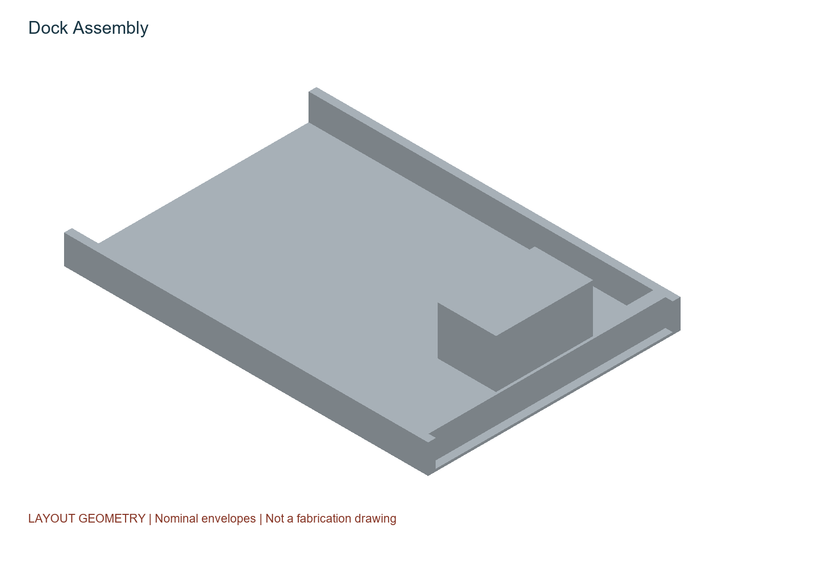
The dock model allocates a 750 × 520 mm platform with guide rails, a stop and a charger housing. Positive parking retention, de-energised charging contacts, interlocks and fault recovery still need engineering. A recognisable dock in CAD does not establish a functioning automatic return system.
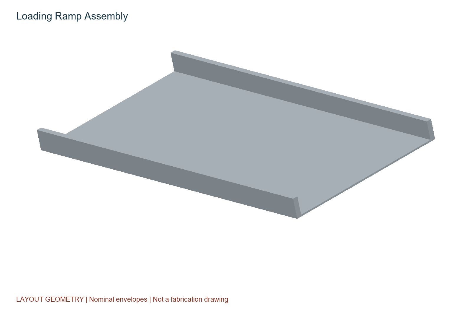
The separate 1 m guided ramp at an assumed 15° gives a nominal rise of sin(15°) × 1 m = 0.259 m. It represents transfer from an adjacent supported platform. It is not a way to climb from ground level onto a roof.
11. Loading and recovery need their own acceptance tests
A loading interface must remain supported through the transfer, limit rollback, avoid catching the cleaning head and retain the robot after power loss. Site anchorage, wind, transfer gaps and recovery access are installation decisions that cannot be finalised from the crawler model alone.
The guided ramp concept gives those questions a visible geometry. The next design iteration needs tolerance stacks, mechanical captures and a test fixture that makes a failed transfer recoverable without putting a person below the robot.
12. An experimental programme that can reject the design
I would begin with restrained ground-level fixtures and representative test surfaces. Before testing, define cleaning, damage, traction and retention acceptance limits with the module supplier and installation owner. The robot must be allowed to fail those criteria without redefining success afterwards.
| Design item | Engineering interpretation |
|---|---|
| Cleaning and abrasion | Control soil type and loading; compare untreated and cleaned specimens; record optical change and surface damage across repeated cycles. |
| Traction and brush load | Measure friction and drag across slope, dust, humidity and contact force. Include turning scrub and repeated starts. |
| Edge and fault behaviour | Inject missing, saturated, disagreeing and stuck sensor signals; measure physical travel and retention after each fault. |
| Energy and thermal | Log current, voltage and temperature through cleaning, turns, stalls, return and charging; compare with the budget. |
| Dock and loader | Test misalignment, interruption, failed latching, power loss and recovery on a restrained fixture. |
Trials should include repeated runs, documented instruments, raw data and uncertainty estimates. Randomising test order can reduce drift bias. Pairing before/after observations helps distinguish a cleaning effect from differences between specimens. A change in irradiance or module temperature must not be misreported as recovered generation.
The current design is useful because its unresolved questions are concrete: friction may be insufficient, the brush may damage a coating, the planner leaves boundary strips, and the electrical integration is incomplete. Each finding can redirect the architecture before production tooling commits the project to it.
13. Exploration before premature limits
When an engineering project is not locked too early into a fixed budget, inherited geometry or assumed design constraints, the possibilities for innovation can feel vast and endless. That freedom is most useful at the exploration stage: it lets me ask whether the architecture itself should change, instead of merely optimising the first answer.
The eventual product still needs limits that can be defended. Physics, safety and evidence do not disappear when a budget expands. I want to keep the imagination open while making each claim precise enough to test.
“Stay Hungry; Stay Foolish” - Steve Jobs. Jobs used the words “Stay hungry. Stay foolish.” in his 2005 Stanford address, recalling the farewell message of the Whole Earth Catalog.
Sources: [4]
Sources and further reading
Project evidence: 20260920-Solar-Panel-Cleaner-Rev00, Design-Contract.json, Calculate.py, coverage.py, engineering reference and verification receipts. Calculations were independently recomputed for publication. Vendor references checked 20 September 2026. All operating figures are assumptions or calculated scenarios; no physical performance or production readiness is claimed. The downloadable models are development CAD, not fabrication instructions.