
· By Sajeevan (Saj) Veeriah
Engineering case study · 3 min read
Designing the Gendio controller around explicit states
An ESP32-S3 display-controller design connecting serial parsing, guarded display output, a four-layer PCB and browser configuration.
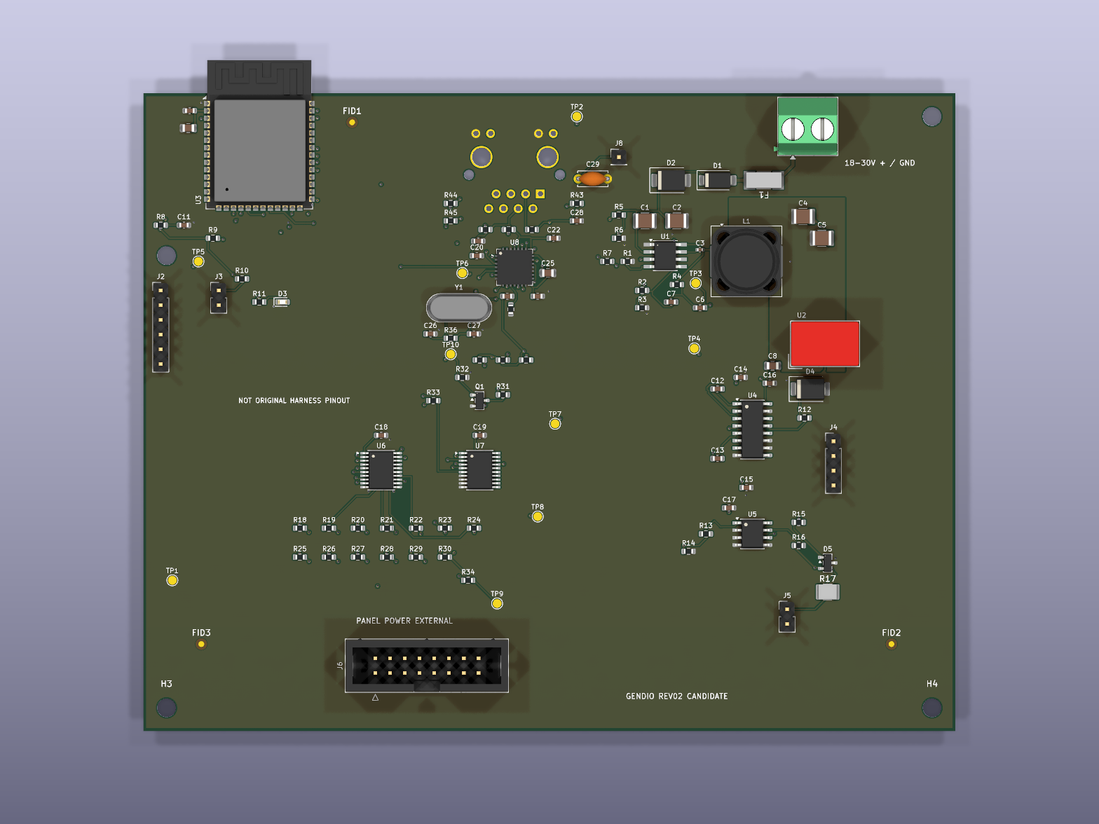
An industrial weight display needs a dependable path from incoming serial data to a readable output. For Gendio, I developed an ESP32-S3 controller design with a custom four-layer PCB, embedded firmware and a local browser configuration interface.
My work covered schematics, PCB layout, firmware, the configuration interface, mechanical exports and automated checks. The public record supports design and software verification; it does not establish assembled-hardware or field validation.
Separating reception from display output
I separated serial parsing, receiver state, display formatting and scanning. Configuration and update handling sit alongside those paths rather than becoming implicit side effects of receiving a value.
The display outputs remain disarmed after boot until explicitly enabled through configuration. Fallback glyphs and invalid-row blanking give the firmware defined behaviour when an input cannot be rendered as intended.
| Boundary | Design responsibility |
|---|---|
| Receive | Handle serial input and maintain receiver state. |
| Interpret | Parse the input independently of display scanning. |
| Display | Format values, apply glyph fallback and guard row output. |
| Configure | Provide local browser controls and explicit activation. |
Sources: [1]
Reviewing the physical design
The four-layer PCB brings together power conversion, processing, serial interfaces and display buffering. I reviewed schematic connectivity, footprints, connector drills and component dissipation. That review led to a fuse-footprint correction and a higher termination-resistor rating.
Mechanical exports connect the board design to mounting and placement work. They support fabrication preparation, but a correct export is not the same as a successful assembly or a verified electrical measurement.
Sources: [1]
What the development checks covered
Synthetic serial fixtures exercised fragmentation, corruption, timeouts, recovery and counter wraparound. Host-based display tests covered glyph fallback, clipping, mirroring, row addressing, clock pulses, disarming and invalid-row blanking.
Browser workflows were exercised against a mocked API. Circuit modelling used ngspice for divider corners, reset timing and fixed-duty LC studies, alongside GNU Octave analytical calculations. Firmware build and image-placement checks covered another part of the integration boundary.
| Evidence | What it supports |
|---|---|
| Synthetic protocol and host tests | Software behaviour for the exercised cases. |
| Mocked browser workflows | Interface behaviour against a controlled API substitute. |
| Circuit models | Behaviour under the model assumptions and analysed conditions. |
| CAD and mechanical exports | Design review and fabrication preparation. |
Sources: [1]
The next evidence needs to come from hardware
These checks reduce uncertainty before hardware trials, but they do not remove it. The next phase would examine an assembled board, real indicator inputs, display timing, loading and thermal behaviour against defined acceptance criteria.
I would retain the separation between model, host test and bench observation in the resulting report. That makes it possible to identify where an assumption failed rather than describing all verification as a single pass.
Why the state boundaries mattered
This project reinforced the value of explicit activation and independently testable paths. A controller should make its operating state understandable to both the firmware and the person configuring it. That is a practical connection between embedded design, human use and verification.
Sources and further reading
Engineering design case study, not a field-validation report, certification statement or peer-reviewed paper. Future hardware work is labelled as proposed.