
Gendio Display Controller
An ESP32-S3 display-controller candidate combining a custom four-layer PCB, serial data handling, matrix-display firmware and a local browser interface for configuration and maintenance.
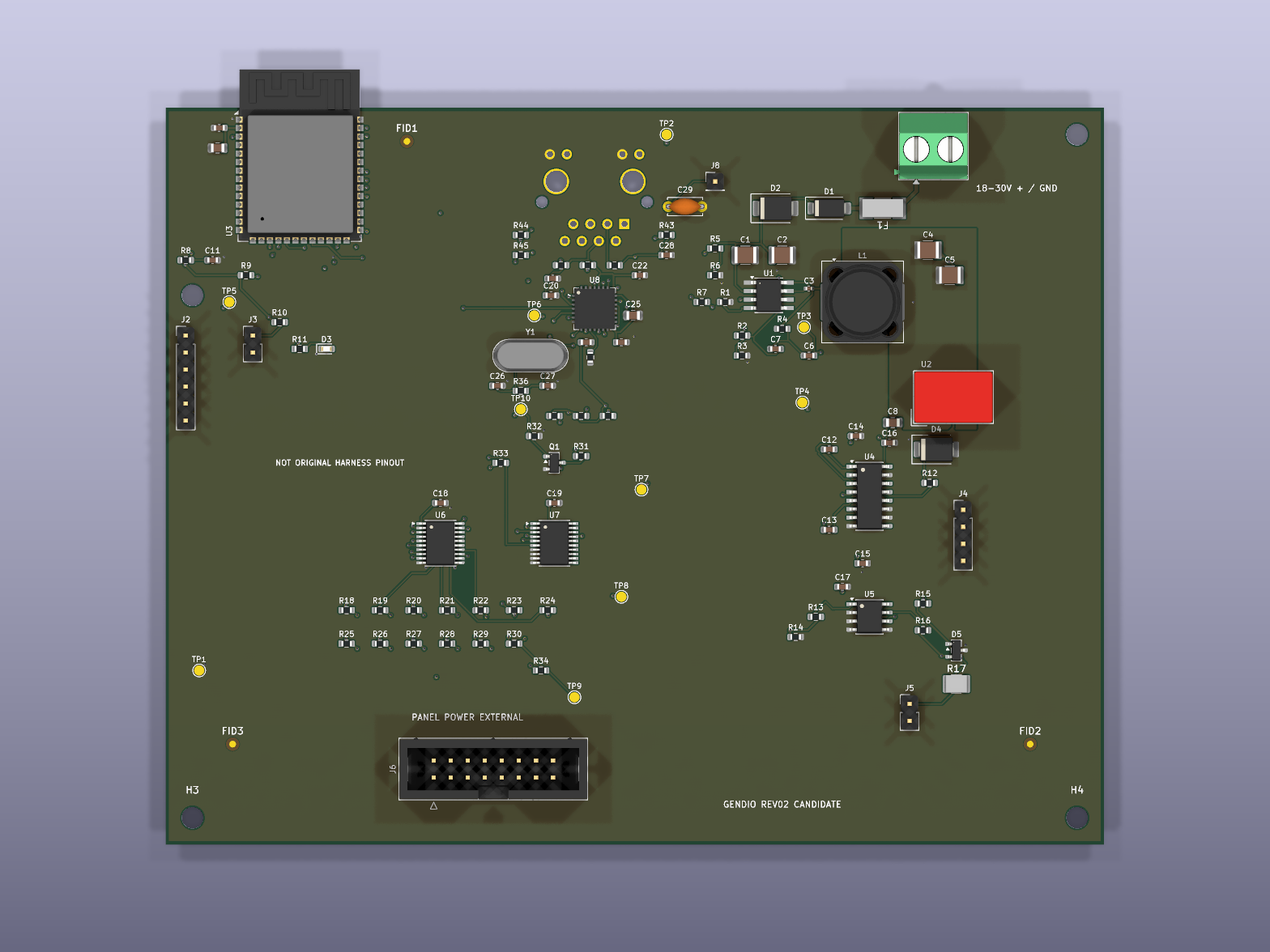
An ESP32-S3 display-controller candidate combining a custom four-layer PCB, serial data handling, matrix-display firmware and a local browser interface for configuration and maintenance.
Developing a replacement controller for an industrial weight display requires the electrical design, incoming data, display timing and commissioning workflow to agree. The original internal panel interface still needs measurement before compatibility can be established.
An ESP32-S3 display-controller candidate combining a custom four-layer PCB, serial data handling, matrix-display firmware and a local browser interface for configuration and maintenance.
Serial inputs feed a bounded parser and receiver state machine. Display formatting and scanning are separated from configuration and update handling. The PCB brings together power conversion, processing, serial interfaces, display buffering and a limited bench Ethernet path.
The following results were recorded in the supplied engineering evidence dated 15 September 2026. They are source-record results, not new hardware tests performed for this portfolio. Assertion counts include repeated synthetic cases and are not counts of independent physical trials.
Zero reported ERC and DRC violations; zero unconnected items and schematic parity errors.
Recorded KiCad 10.0.6 checks with configured exclusions. Component-specific layout and assembly review remain open.
ESP32-S3 build recorded successfully; offline image identity, partition placement and non-overlap checks passed.
Build and file checks only. No physical flash, boot or interrupted-update recovery test.
350 protocol assertions and 61,234 extended assertions passed across 31 synthetic profiles.
Synthetic fixtures cover fragmentation, corruption, timeouts, recovery and counter wraparound. Real indicator captures are still required.
Glyph fallback, clipping, mirroring, row addressing, clock pulses, disarming and invalid-row blanking passed.
Host framebuffer and GPIO simulation. Panel timing, brightness and electrical behaviour were not measured.
31 protocol options and five POST workflows checked; no reported JavaScript errors or mobile horizontal overflow.
Mocked API responses. Does not establish live authentication, radio operation or device update reliability.
Ten ngspice studies passed their numerical bounds: divider corners, reset timing and six fixed-duty LC cases.
Idealised subcircuits. The regulator control law, radio transients and display load are excluded.
GNU Octave execution completed with three numerical assertions passing.
Analytical load-step and tolerance studies. The plotted waveform is a model response, not a board measurement.
Vendor-model attempts failed to converge or produced invalid output; no validated full-regulator result.
Requires a compatible model/simulator and physical power-stage verification.
Supplementary findings were triaged; layout and environmental acceptance remain open.
Some automated flags were identified as false positives. The thermal report evaluated no components and is not a thermal pass.
Board model and mounting exports prepared; 88 SMT designators matched the draft placement file.
Simplified component envelopes, unverified enclosure/harness fit and unresolved procurement prevent production acceptance.
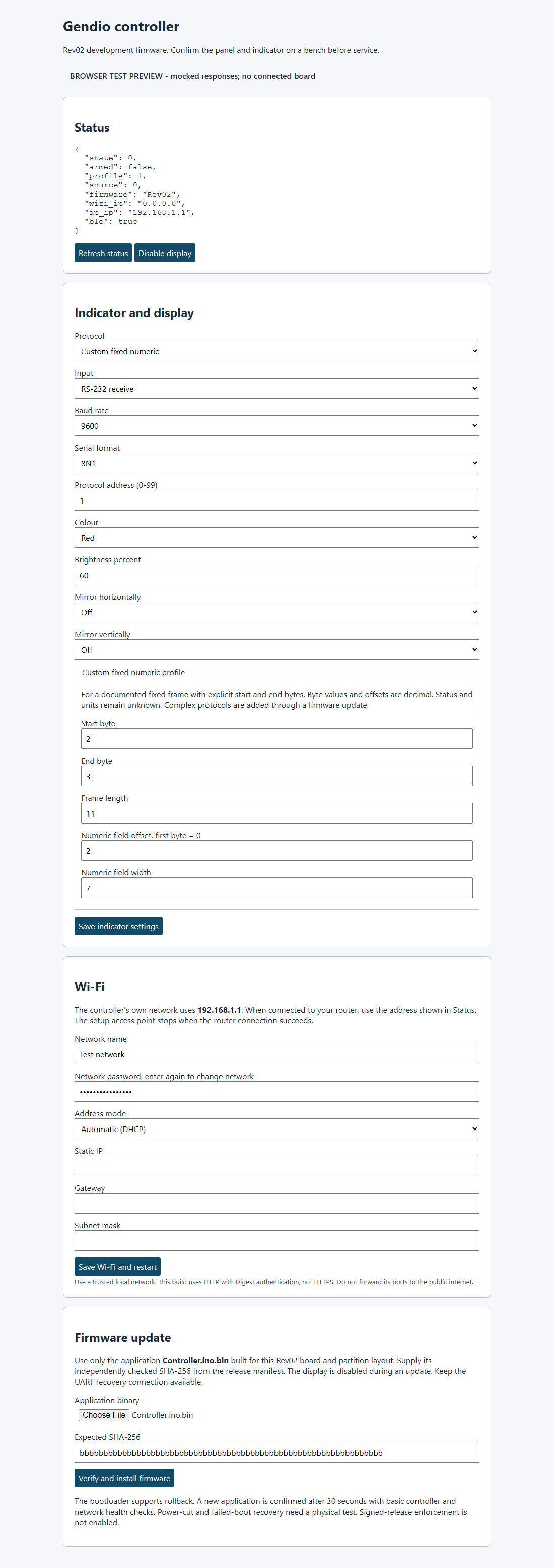
The local interface groups commissioning and maintenance controls. This capture uses test responses with no connected board; visible values are test inputs, not deployment settings.
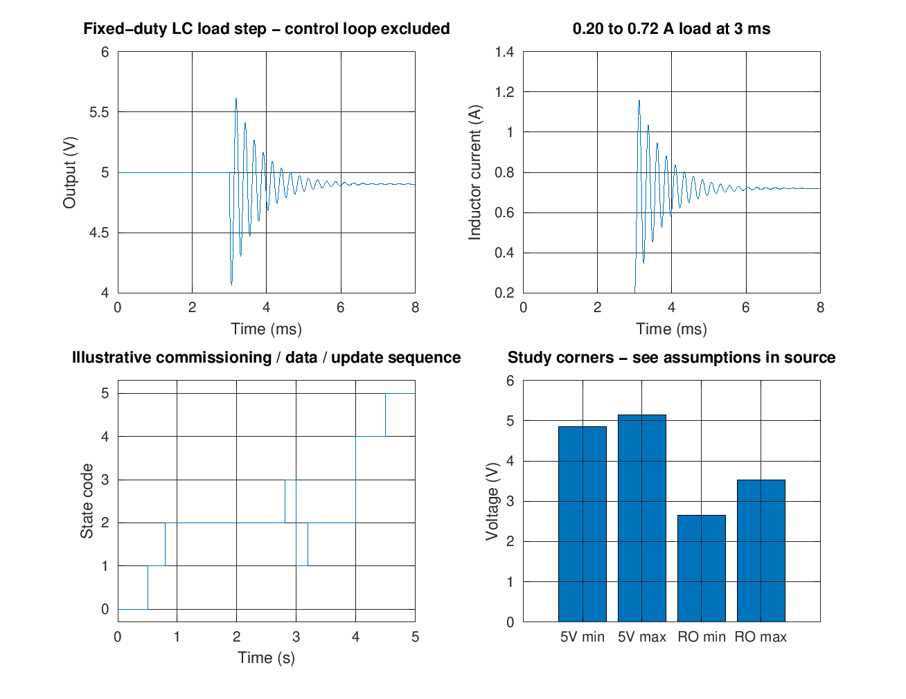
The load-step model oscillates and settles near 4.90 V. It excludes the regulator control loop. The state sequence is illustrative, and the corner values depend on selected study assumptions.
Engineering candidate. Physical bring-up and production acceptance remain outstanding.
No assembled board was available in the evidence package. Original panel mapping and timing, full-regulator behaviour, enclosure fit, procurement, thermal performance, EMC, surge, radio behaviour, update recovery and endurance remain open. Native rule checks use configured exclusions and do not establish complete design acceptance. Full schematics, PCB source, manufacturing exports, BOM, firmware and raw diagnostic records remain private.
Discuss this work, compare it with your engineering brief, or continue to the next evidence record.